
WHAT IS ROOM RESONANCES CALCULATOR?
DATA ENTRY
In order to create the report, the Room Resonance Calculator needs some information about the project. Cinema Tools does not store or record any data that is entered into this form.
ID DETAILS
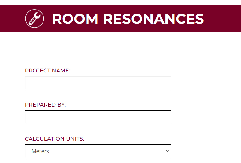
Project Name:
Enter the project name so that the report can be easily identified
Prepared By:
Enter the name of the person creating the report
Calculation Units:
Select the measurement units that will be used in the other form fields
PROJECT DATA

ROOM DIMENSIONS
Length:
Enter the length of the room using the units selected for this calculator
Width:
Enter the width of the room using the units selected for this calculator
Height:
Enter the height of the room using the units selected for this calculator
DEFAULT DATA
NONE
REPORT CONTENT
Page 1 – Title Page
The Title page of the report is used to show:
Calculator Name: Projector Location
Project Name: As entered on the data entry page
Prepared By: As entered on the data entry page
Page 2 – Room Resonances: Resonance Distribution

The Room Resonances Resonance Distribution page of the report is used to show all of the resonances calculated for the given room size.
The calculator also runs a check on the resonance distribution using the Walker Criteria formula which helps to identify if the distribution of the length, width and height resonances are well separated or if they interact with each other.
The right hand data bar details:
Project Name
Room Length in the units selected for the calculator
Room Width in the units selected for the calculator
Room Height in the units selected for the calculator
Pass or Fail of the Walker Criteria calculations
Colour Key to identify each of the calculated room resonance categories
Page 3 – Room Resonances: Axial Resonance 1
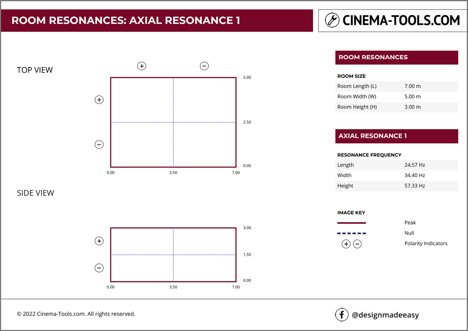
The Room Resonances: Axial Resonance 1 page of the report is used to show the frequency and spatial distribution of the first resonance.
An axial resonance is one which forms between two surfaces within the room – specifically along the length the width or the height of the room.
The first result on this page shows the Top View of the room with the bottom left corner being location 0,0. This means the front wall is on the left of the top view. Length dimensions are marked along the lower side of the view and width dimensions are marked along the right side of the view.
The second result on this page shows the Side View of the room. The front wall on the left of the side view. Length dimensions are marked along the lower side of the view and height dimensions are marked along the right side of the view.
The solid lines on the drawing indicate where the resonance has a pressure peak.
For Axial Resonance 1 those are found at the perimeter of the room.
The dashed lines on the drawing indicate where the resonance has a pressure Null.
For Axial Resonance 1 those are found at the mid lines of the room.
The polarity indicators show how a subwoofer placed in one section will interact with a subwoofer placed in another section. The polarity changes at at each null crossing point.
The right hand data bar details:
Project Name
Room Length in the units selected for the calculator
Room Width in the units selected for the calculator
Room Height in the units selected for the calculator
Frequency Data for Axial Resonance 1
Resonance Frequency Length in Hz
Resonance Frequency Width in Hz
Resonance Frequency Height in Hz
Colour Key to identify each of the elements on the room views
Page 4 – Room Resonances: Axial Resonance 2

The Room Resonances: Axial Resonance 2 page of the report is used to show the frequency and spatial distribution of the second resonance.
An axial resonance is one which forms between two surfaces within the room – specifically along the length the width or the height of the room.
The first result on this page shows the Top View of the room with the bottom left corner being location 0,0. This means the front wall is on the left of the top view. Length dimensions are marked along the lower side of the view and width dimensions are marked along the right side of the view.
The second result on this page shows the Side View of the room. The front wall on the left of the side view. Length dimensions are marked along the lower side of the view and height dimensions are marked along the right side of the view.
The solid lines on the drawing indicate where the resonance has a pressure peak.
For Axial Resonance 2 those are found at the perimeter and mid lines of the room.
The dashed lines on the drawing indicate where the resonance has a pressure Null.
For Axial Resonance 2 those are found at the quarter lines of the room.
The polarity indicators show how a subwoofer placed in one section will interact with a subwoofer placed in another section. The polarity changes at at each null crossing point.
The right hand data bar details:
Project Name
Room Length in the units selected for the calculator
Room Width in the units selected for the calculator
Room Height in the units selected for the calculator
Frequency Data for Axial Resonance 2
Resonance Frequency Length in Hz
Resonance Frequency Width in Hz
Resonance Frequency Height in Hz
Colour Key to identify each of the elements on the room views
Page 5 – Room Resonances: Axial Resonance 3

The Room Resonances: Axial Resonance 3 page of the report is used to show the frequency and spatial distribution of the third resonance.
An axial resonance is one which forms between two surfaces within the room – specifically along the length the width or the height of the room.
The first result on this page shows the Top View of the room with the bottom left corner being location 0,0. This means the front wall is on the left of the top view. Length dimensions are marked along the lower side of the view and width dimensions are marked along the right side of the view.
The second result on this page shows the Side View of the room. The front wall on the left of the side view. Length
dimensions are marked along the lower side of the view and height dimensions are marked along the right side of the view.
The solid lines on the drawing indicate where the resonance has a pressure peak.
For Axial Resoance 3 those are found at the perimter and third lines of the room.
The dashed lines on the drawing indicate where the resonance has a pressure Null.
For Axial Resoance 3 those are found at the sixth lines of the room.
The polarity indicators show how a subwoofer placed in one section will interact with a subwoofer placed in another section. The polarity changes at at each null crossing point.
The right hand data bar details:
Project Name
Room Length in the units selected for the calculator
Room Width in the units selected for the calculator
Room Height in the units selected for the calculator
Frequency Data for Axial Resonance 3
Resoance Frequency Length in Hz
Resoance Frequency Width in Hz
Resoance Frequency Height in Hz
Colour Key to identify each of the elements on the room views
Page 6 – Room Resonances: Axial Resonance 4
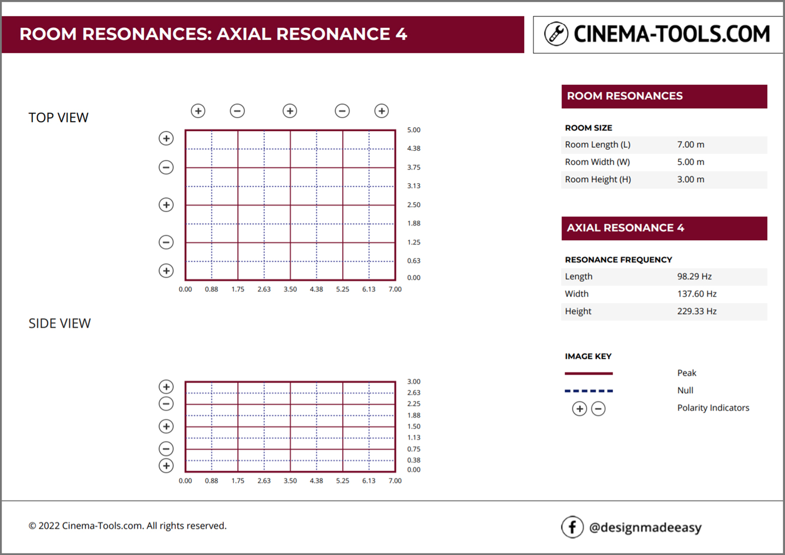
The Room Resonances: Axial Resonance 4 page of the report is used to show the frequency and spatial distribution of the third resonance.
An axial resonance is one which forms between two surfaces within the room – specifically along the length the width or the height of the room.
The first result on this page shows the Top View of the room with the bottom left corner being location 0,0. This means the front wall is on the left of the top view. Length dimensions are marked along the lower side of the view and width dimensions are marked along the right side of the view.
The second result on this page shows the Side View of the room. The front wall on the left of the side view. Length dimensions are marked along the lower side of the view and height dimensions are marked along the right side of the view.
The solid lines on the drawing indicate where the resonance has a pressure peak.
For Axial Resonance 4 those are found at the perimeter, mid and quarter lines of the room.
The dashed lines on the drawing indicate where the resonance has a pressure Null.
For Axial Resonance 4 those are found at the eighth lines of the room.
The polarity indicators show how a subwoofer placed in one section will interact with a subwoofer placed in another section. The polarity changes at at each null crossing point.
The right hand data bar details:
Project Name
Room Length in the units selected for the calculator
Room Width in the units selected for the calculator
Room Height in the units selected for the calculator
Frequency Data for Axial Resonance 4
Resonance Frequency Length in Hz
Resonance Frequency Width in Hz
Resonance Frequency Height in Hz
Colour Key to identify each of the elements on the room views
Page 7 – Closing Page

The closing page is used to highlight the Cinema Tools facebook page designmadeeasy

ROOM RESONANCES CALCULATOR IS A FREE TOOL